2023. 4. 4. 16:48ㆍARM
RISC(Reduced Instruction Set Computer) : 적은 수의 명령어를 사용하며 명령어의 길이를 통일한 컴퓨터 구조이다. 단순한 명령어는 빠르게 실행할 수 있지만 복잡한 명령을 실행할 땐 CISC보다 처리 속도가 느리다. 실수 연산을 주로 하는 슈퍼컴퓨터의 CPU용으로 개발되었다. ARM, AVR등이 RISC 구조이다.
CISC(Complex Instruction Set Computer) : 다양한 명령어를 사용하는 컴퓨터 구조이다. RISC보다 명령어의 실행 속도는 떨어지지만, 복잡하고 다양한 명령을 수행할 수 있어 범용 컴퓨터의 CPU를 만드는데 주로 쓰인다.
HAL 드라이버
AVR에서는 MCU의 레지스터에 직접 접근하는 방식으로 프로그램을 하였지만, STM32에서는 제조사에서 제공하는 함수를 이용해 MCU의 주변장치들을 제어할 수 있다.
STMCUBE IDE
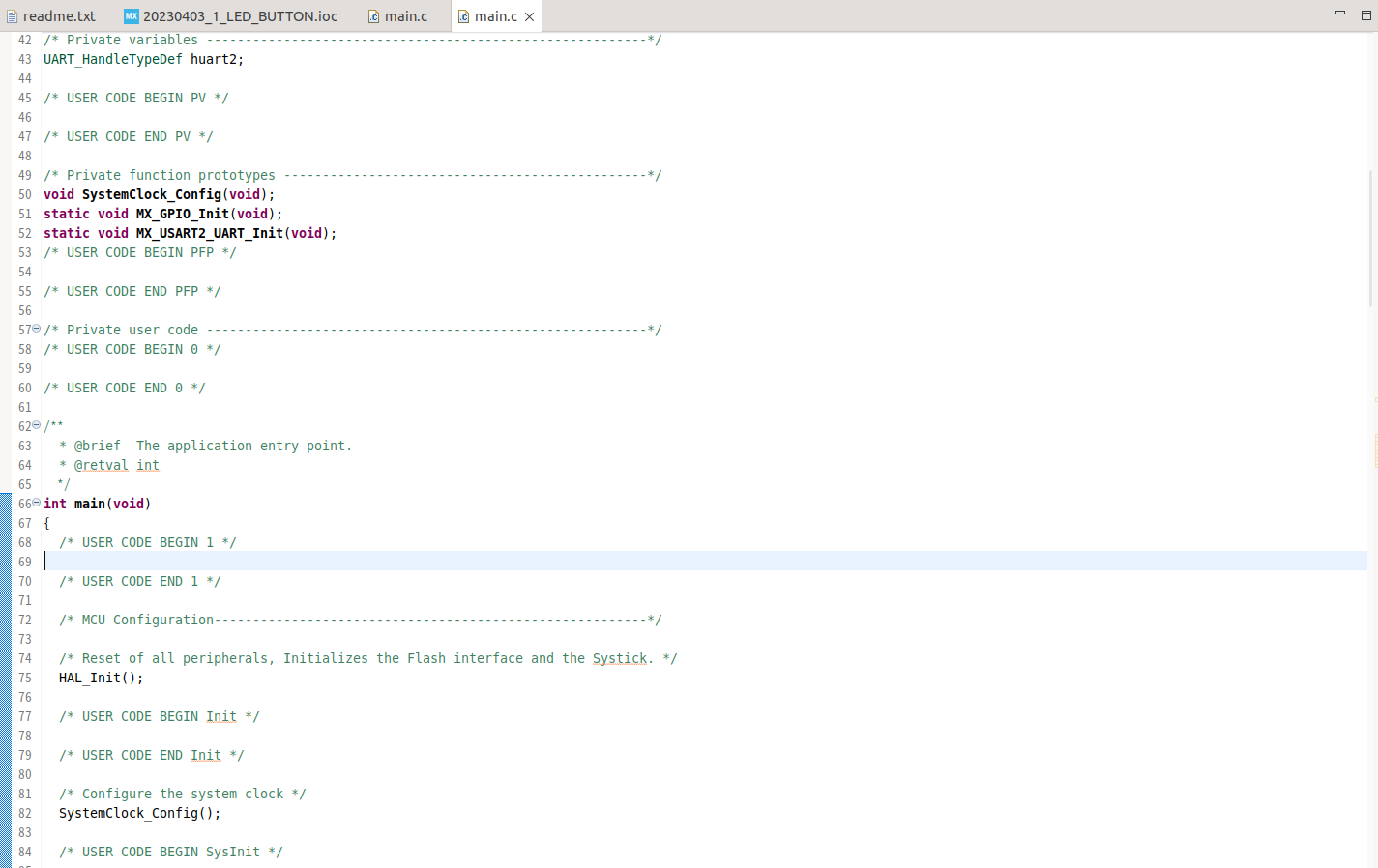
프로젝트를 생성한 모습이다. 사용자가 작성하는 코드는 꼭 위의 USERCODE 주석 사이에 작성해야 한다. 그렇지 않으면 IDE에서 컴파일할 때 코드가 꼬일 수 있다.
#if 1
    if(HAL_GPIO_ReadPin(GPIOC, GPIO_PIN_13) == GPIO_PIN_RESET){
	  HAL_GPIO_TogglePin(GPIOA, GPIO_PIN_5);
	  HAL_Delay(500);
    }
위 코드는 내부 버튼이 눌릴 때마다 LED의 상태가 바뀌는 코드이다. 직접 레지스터를 읽었던 AVR과 달리 함수로 엑세스하는 것을 볼 수 있다.
HAL_GPIO_WritePin(GPIOB, 0xff, GPIO_PIN_SET);GPIO Write 함수는 (포트, 핀번호, 출력할 값)순으로 값을 입력한다. 핀번호는 10진수로 2, 3 입력하는게 아닌 AVR의 핀번호를 지정하는 것처럼 사용한다. 2바이트의 16진수를 사용해서 사용하고싶은 핀을 지정하면 된다. 출력할 값은 0과 1중 하나이다.
HAL_GPIO_ReadPin(GPIOC, GPIO_PIN_0)GPIO Read 함수도 마찬가지로 (포트, 핀번호)로 사용하면 된다.
Timer
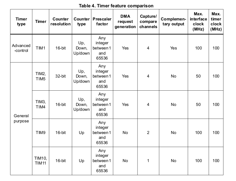
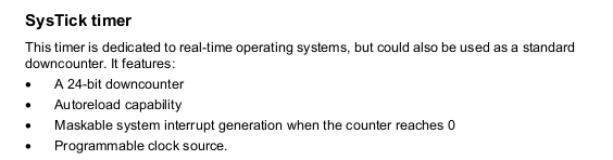
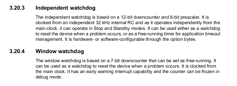
타이머는 일반 타이머 8개와 2개의 워치도그 타이머, 그리고 시스틱 타이머가 있다. 시스틱 타이머는 ARM의 디폴트 타이머이다.
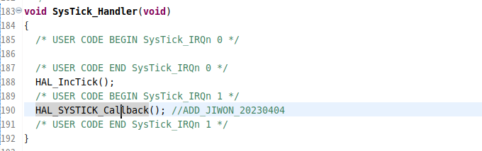
stm32f4xx_it.c 에 있는 시스틱 핸들러 함수를 찾아간후 콜백함수를 핸들러에 등록한다.
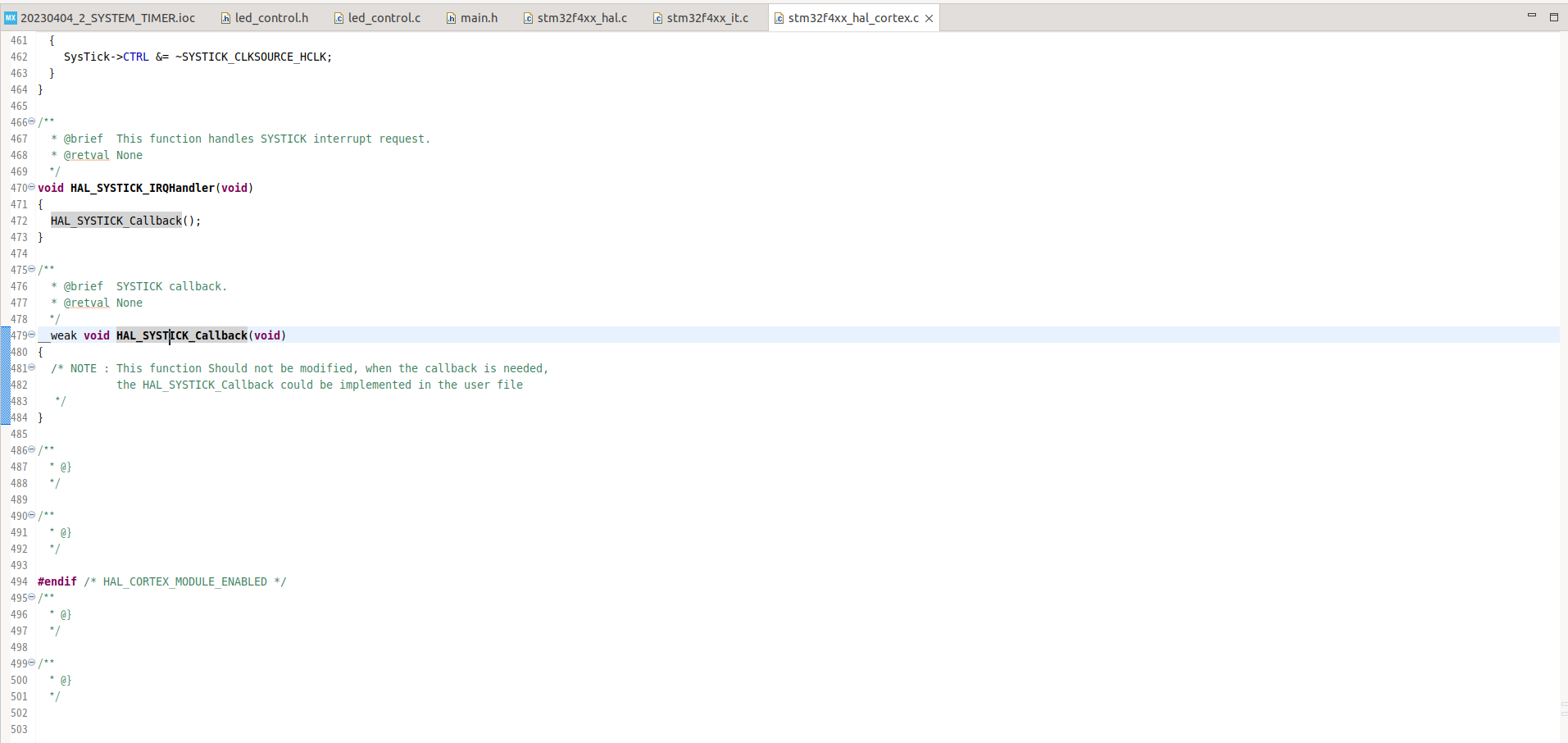
그 후 stm32f4xx_hal_cortex.c 에 있는 콜백함수를 찾아가 잘래내기한 후 main.c의 코드 작성 부분에 붙여넣는다.
/* USER CODE BEGIN Header */
/**
  ******************************************************************************
  * @file           : main.c
  * @brief          : Main program body
  ******************************************************************************
  * @attention
  *
  * Copyright (c) 2023 STMicroelectronics.
  * All rights reserved.
  *
  * This software is licensed under terms that can be found in the LICENSE file
  * in the root directory of this software component.
  * If no LICENSE file comes with this software, it is provided AS-IS.
  *
  ******************************************************************************
  */
/* USER CODE END Header */
/* Includes ------------------------------------------------------------------*/
#include "main.h"

/* Private includes ----------------------------------------------------------*/
/* USER CODE BEGIN Includes */
#include "led_control.h"
/* USER CODE END Includes */

/* Private typedef -----------------------------------------------------------*/
/* USER CODE BEGIN PTD */

/* USER CODE END PTD */

/* Private define ------------------------------------------------------------*/
/* USER CODE BEGIN PD */

/* USER CODE END PD */

/* Private macro -------------------------------------------------------------*/
/* USER CODE BEGIN PM */

/* USER CODE END PM */

/* Private variables ---------------------------------------------------------*/
UART_HandleTypeDef huart2;

/* USER CODE BEGIN PV */

/* USER CODE END PV */

/* Private function prototypes -----------------------------------------------*/
void SystemClock_Config(void);
static void MX_GPIO_Init(void);
static void MX_USART2_UART_Init(void);
/* USER CODE BEGIN PFP */

extern void led_main();
extern void led_all_on();
extern void led_all_off();
extern void led_blink_up();
extern void led_blink_down();
extern void led_flower_on();
extern void led_flower_off();
extern uint32_t prev;
extern void one_button_processing();
extern void led_sequential_up();
extern void led_sequential_down();
/* USER CODE END PFP */

/* Private user code ---------------------------------------------------------*/
/* USER CODE BEGIN 0 */
/*
1. call by SysTick_Handler of stm32f4xx_it.c
2. add void HAL_SYSTICK_Callback(void) in main.c
3. move to here

Arm default timer - it will enter here every 1ms
*/
volatile unsigned int timer_1ms = 0;
 void HAL_SYSTICK_Callback(void)
{
  timer_1ms ++;
}

/* USER CODE END 0 */

/**
  * @brief  The application entry point.
  * @retval int
  */
int main(void)
{
  /* USER CODE BEGIN 1 */
  /* USER CODE END 1 */

  /* MCU Configuration--------------------------------------------------------*/

  /* Reset of all peripherals, Initializes the Flash interface and the Systick. */
  HAL_Init();

  /* USER CODE BEGIN Init */
 prev = HAL_GetTick();
  /* USER CODE END Init */

  /* Configure the system clock */
  SystemClock_Config();

  /* USER CODE BEGIN SysInit */

  /* USER CODE END SysInit */

  /* Initialize all configured peripherals */
  MX_GPIO_Init();
  MX_USART2_UART_Init();
  /* USER CODE BEGIN 2 */

  /* USER CODE END 2 */

  /* Infinite loop */
  /* USER CODE BEGIN WHILE */
  while (1)
  {
#if 1
	  led_main();

#endif
  }
}
/**
  * @brief System Clock Configuration
  * @retval None
  */
void SystemClock_Config(void)
{
  RCC_OscInitTypeDef RCC_OscInitStruct = {0};
  RCC_ClkInitTypeDef RCC_ClkInitStruct = {0};

  /** Configure the main internal regulator output voltage
  */
  __HAL_RCC_PWR_CLK_ENABLE();
  __HAL_PWR_VOLTAGESCALING_CONFIG(PWR_REGULATOR_VOLTAGE_SCALE1);

  /** Initializes the RCC Oscillators according to the specified parameters
  * in the RCC_OscInitTypeDef structure.
  */
  RCC_OscInitStruct.OscillatorType = RCC_OSCILLATORTYPE_HSI;
  RCC_OscInitStruct.HSIState = RCC_HSI_ON;
  RCC_OscInitStruct.HSICalibrationValue = RCC_HSICALIBRATION_DEFAULT;
  RCC_OscInitStruct.PLL.PLLState = RCC_PLL_ON;
  RCC_OscInitStruct.PLL.PLLSource = RCC_PLLSOURCE_HSI;
  RCC_OscInitStruct.PLL.PLLM = 16;
  RCC_OscInitStruct.PLL.PLLN = 336;
  RCC_OscInitStruct.PLL.PLLP = RCC_PLLP_DIV4;
  RCC_OscInitStruct.PLL.PLLQ = 4;
  if (HAL_RCC_OscConfig(&RCC_OscInitStruct) != HAL_OK)
  {
    Error_Handler();
  }

  /** Initializes the CPU, AHB and APB buses clocks
  */
  RCC_ClkInitStruct.ClockType = RCC_CLOCKTYPE_HCLK|RCC_CLOCKTYPE_SYSCLK
                              |RCC_CLOCKTYPE_PCLK1|RCC_CLOCKTYPE_PCLK2;
  RCC_ClkInitStruct.SYSCLKSource = RCC_SYSCLKSOURCE_PLLCLK;
  RCC_ClkInitStruct.AHBCLKDivider = RCC_SYSCLK_DIV1;
  RCC_ClkInitStruct.APB1CLKDivider = RCC_HCLK_DIV2;
  RCC_ClkInitStruct.APB2CLKDivider = RCC_HCLK_DIV1;

  if (HAL_RCC_ClockConfig(&RCC_ClkInitStruct, FLASH_LATENCY_2) != HAL_OK)
  {
    Error_Handler();
  }
}

/**
  * @brief USART2 Initialization Function
  * @param None
  * @retval None
  */
static void MX_USART2_UART_Init(void)
{

  /* USER CODE BEGIN USART2_Init 0 */

  /* USER CODE END USART2_Init 0 */

  /* USER CODE BEGIN USART2_Init 1 */

  /* USER CODE END USART2_Init 1 */
  huart2.Instance = USART2;
  huart2.Init.BaudRate = 115200;
  huart2.Init.WordLength = UART_WORDLENGTH_8B;
  huart2.Init.StopBits = UART_STOPBITS_1;
  huart2.Init.Parity = UART_PARITY_NONE;
  huart2.Init.Mode = UART_MODE_TX_RX;
  huart2.Init.HwFlowCtl = UART_HWCONTROL_NONE;
  huart2.Init.OverSampling = UART_OVERSAMPLING_16;
  if (HAL_UART_Init(&huart2) != HAL_OK)
  {
    Error_Handler();
  }
  /* USER CODE BEGIN USART2_Init 2 */

  /* USER CODE END USART2_Init 2 */

}

/**
  * @brief GPIO Initialization Function
  * @param None
  * @retval None
  */
static void MX_GPIO_Init(void)
{
  GPIO_InitTypeDef GPIO_InitStruct = {0};
/* USER CODE BEGIN MX_GPIO_Init_1 */
/* USER CODE END MX_GPIO_Init_1 */

  /* GPIO Ports Clock Enable */
  __HAL_RCC_GPIOC_CLK_ENABLE();
  __HAL_RCC_GPIOH_CLK_ENABLE();
  __HAL_RCC_GPIOA_CLK_ENABLE();
  __HAL_RCC_GPIOB_CLK_ENABLE();

  /*Configure GPIO pin Output Level */
  HAL_GPIO_WritePin(LD2_GPIO_Port, LD2_Pin, GPIO_PIN_RESET);

  /*Configure GPIO pin Output Level */
  HAL_GPIO_WritePin(GPIOB, led0_Pin|led1_Pin|led2_Pin|led3_Pin
                          |led4_Pin|led5_Pin|led6_Pin|led7_Pin, GPIO_PIN_RESET);

  /*Configure GPIO pin : B1_Pin */
  GPIO_InitStruct.Pin = B1_Pin;
  GPIO_InitStruct.Mode = GPIO_MODE_IT_FALLING;
  GPIO_InitStruct.Pull = GPIO_NOPULL;
  HAL_GPIO_Init(B1_GPIO_Port, &GPIO_InitStruct);

  /*Configure GPIO pins : PC0 PC1 btn2_Pin */
  GPIO_InitStruct.Pin = GPIO_PIN_0|GPIO_PIN_1|btn2_Pin;
  GPIO_InitStruct.Mode = GPIO_MODE_INPUT;
  GPIO_InitStruct.Pull = GPIO_NOPULL;
  HAL_GPIO_Init(GPIOC, &GPIO_InitStruct);

  /*Configure GPIO pin : LD2_Pin */
  GPIO_InitStruct.Pin = LD2_Pin;
  GPIO_InitStruct.Mode = GPIO_MODE_OUTPUT_PP;
  GPIO_InitStruct.Pull = GPIO_NOPULL;
  GPIO_InitStruct.Speed = GPIO_SPEED_FREQ_LOW;
  HAL_GPIO_Init(LD2_GPIO_Port, &GPIO_InitStruct);

  /*Configure GPIO pins : led0_Pin led1_Pin led2_Pin led3_Pin
                           led4_Pin led5_Pin led6_Pin led7_Pin */
  GPIO_InitStruct.Pin = led0_Pin|led1_Pin|led2_Pin|led3_Pin
                          |led4_Pin|led5_Pin|led6_Pin|led7_Pin;
  GPIO_InitStruct.Mode = GPIO_MODE_OUTPUT_PP;
  GPIO_InitStruct.Pull = GPIO_NOPULL;
  GPIO_InitStruct.Speed = GPIO_SPEED_FREQ_LOW;
  HAL_GPIO_Init(GPIOB, &GPIO_InitStruct);

/* USER CODE BEGIN MX_GPIO_Init_2 */
/* USER CODE END MX_GPIO_Init_2 */
}

/* USER CODE BEGIN 4 */

/* USER CODE END 4 */

/**
  * @brief  This function is executed in case of error occurrence.
  * @retval None
  */
void Error_Handler(void)
{
  /* USER CODE BEGIN Error_Handler_Debug */
  /* User can add his own implementation to report the HAL error return state */
  __disable_irq();
  while (1)
  {
  }
  /* USER CODE END Error_Handler_Debug */
}

#ifdef  USE_FULL_ASSERT
/**
  * @brief  Reports the name of the source file and the source line number
  *         where the assert_param error has occurred.
  * @param  file: pointer to the source file name
  * @param  line: assert_param error line source number
  * @retval None
  */
void assert_failed(uint8_t *file, uint32_t line)
{
  /* USER CODE BEGIN 6 */
  /* User can add his own implementation to report the file name and line number,
     ex: printf("Wrong parameters value: file %s on line %d\r\n", file, line) */
  /* USER CODE END 6 */
}
#endif /* USE_FULL_ASSERT */
이후 led를 컨트롤하는 led control.c 에 extern 형으로 추가해준다.
/*
 * led_control.c
 *
 *  Created on: Apr 3, 2023
 *      Author: jiwon
 */


#include "led_control.h"
#include "stdint.h"

uint8_t state = 0;
uint8_t tmp = 0;
uint32_t prev, curr;

extern unsigned char current_button_status[BUTTON_NUMBER];
extern volatile unsigned int timer_1ms;

int led_indecator = 0;
void led_all_on_off()
{
	if(timer_1ms >= 500)
	{
		if(!led_indecator){
			led_all_on();
			led_indecator = 1;
		}
		else{
			led_all_off();
			led_indecator = 0;
	    }
	timer_1ms = 0;
	}
}
void led_main()
{
	timer_1ms = 0;
	while(1)
	{
		led_all_off();
		HAL_Delay(500);
		led_all_on();
		HAL_Delay(500);
	}
    HAL_Delay(500);
}

void led_all_on()
{
    HAL_GPIO_WritePin(GPIOB, 0xff, GPIO_PIN_SET);

}

void led_all_off()
{
    HAL_GPIO_WritePin(GPIOB, 0xff, GPIO_PIN_RESET);

}
위 코드를 작성하면 0.5초마다 LED가 깜빡거린다.
General purpose timer - timer 11
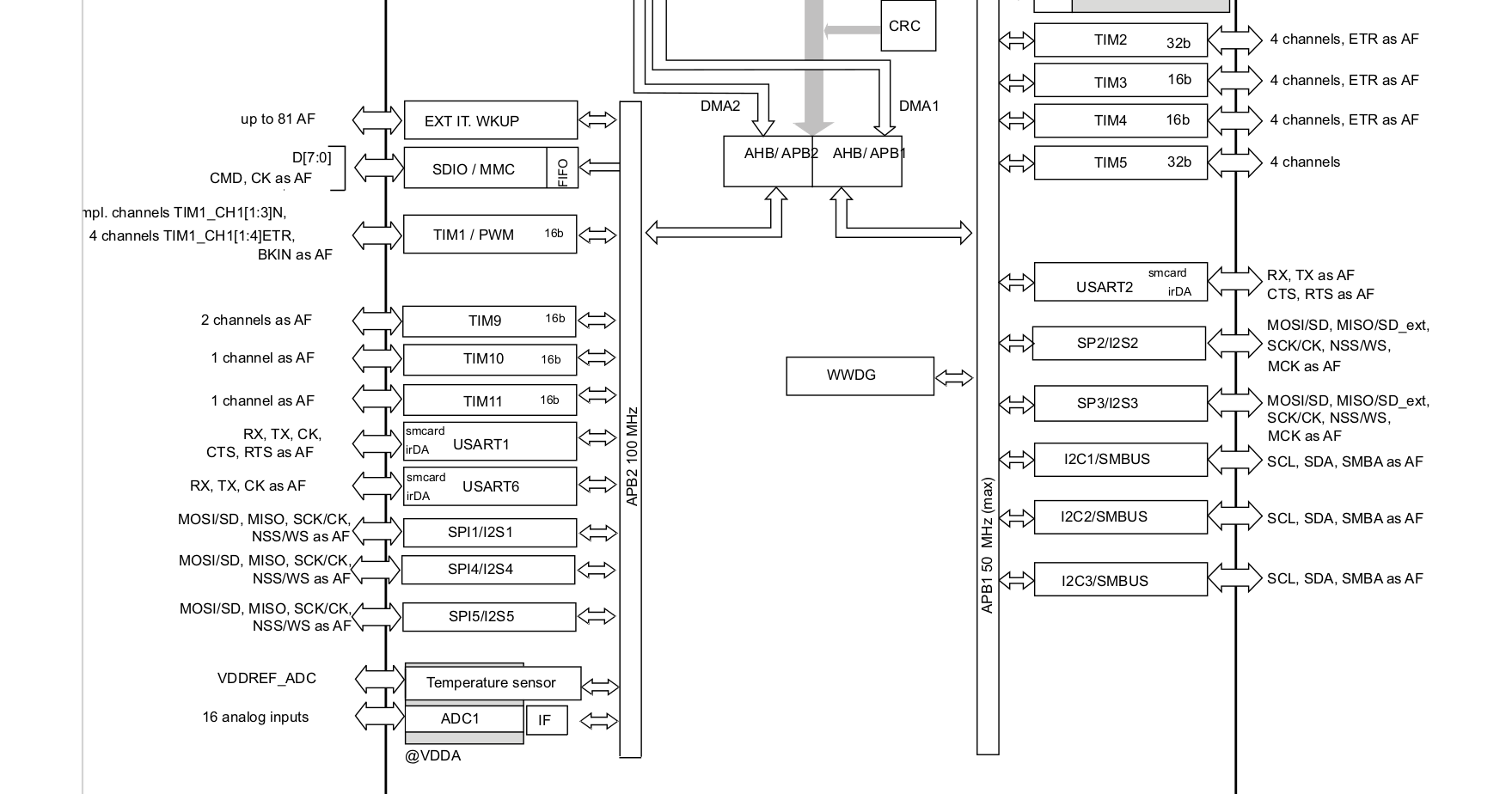
timer 11은 16비트 타이머로, 100Mhz의 APB2에 연결되어있다.
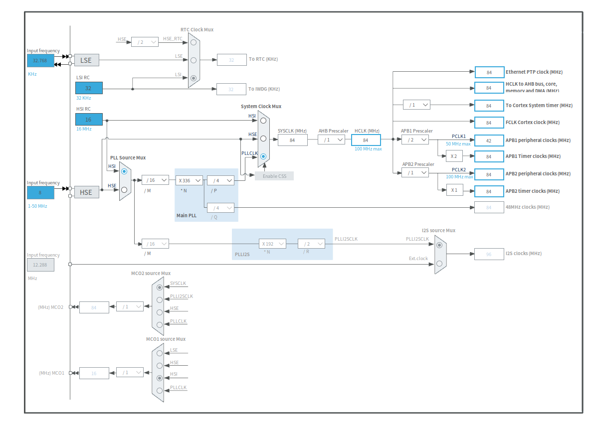
- 체배(multiply) : 원래의 주파수보다 큰 주파수를 가진 신호로 만드는 것, 하드웨어 로직(PLL 로직)이 필요함
- 분주(devider) : 원래의 주파수보다 작은 주파수를 가진 신호로 만드는것
위의 config 화면에서 84Mhz로 설정하면, APB1에는 42Mhz, APB2에는 84Mhz가 그대로 들어가는 것을 볼 수 있다. timer11은 APB2에 연결되어 있으므로, 84Mhz로 동작한다.
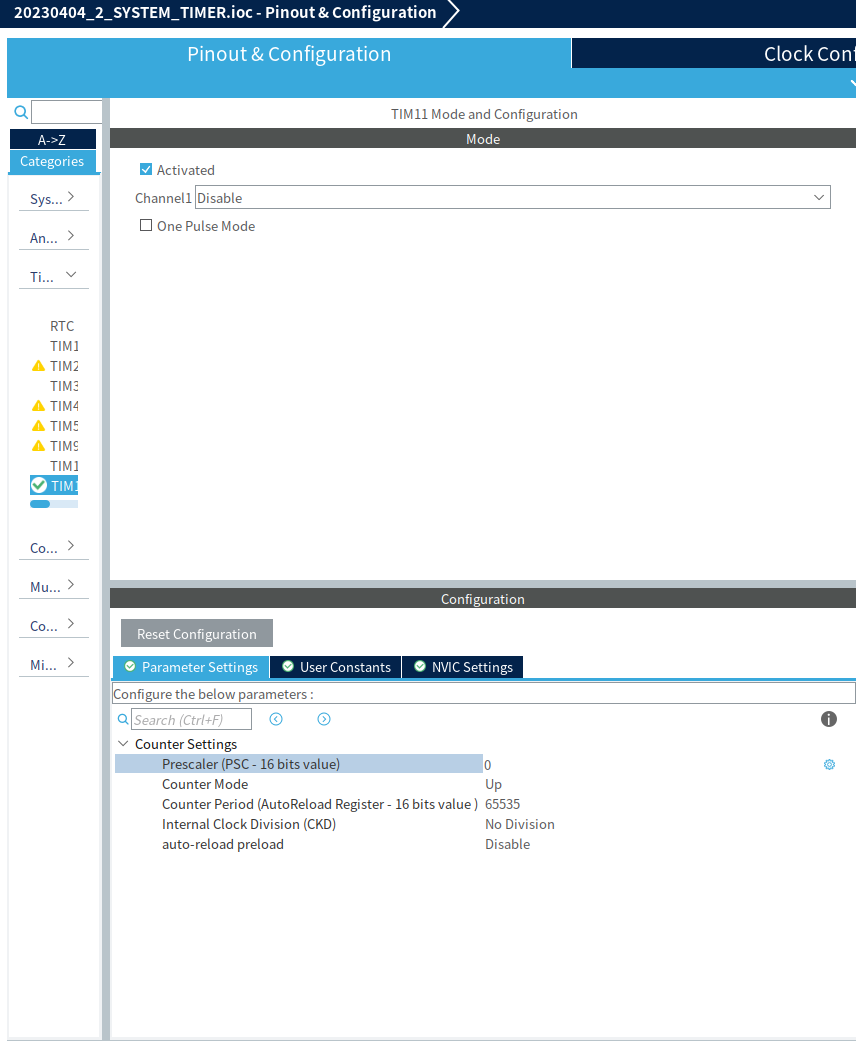
위 화면에서 분주비와 카운터 모드를 선택할 수 있다. 1Mhz로 분주하려고 한다.
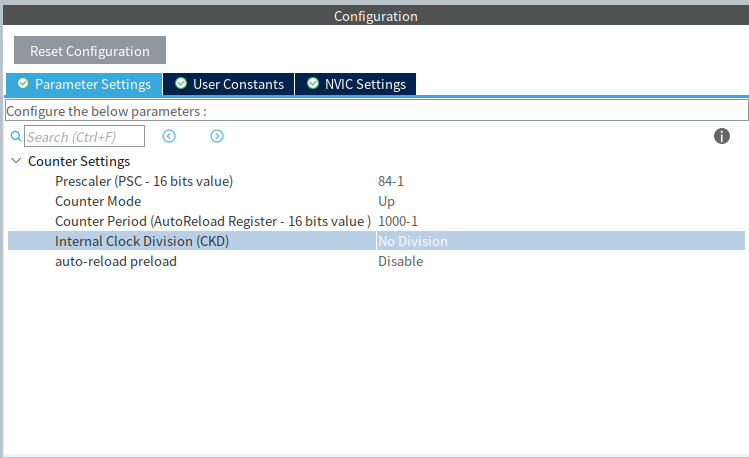
위 설정을 마치면 main.c에 timer11에 대한 구조체가 만들어지게 된다.
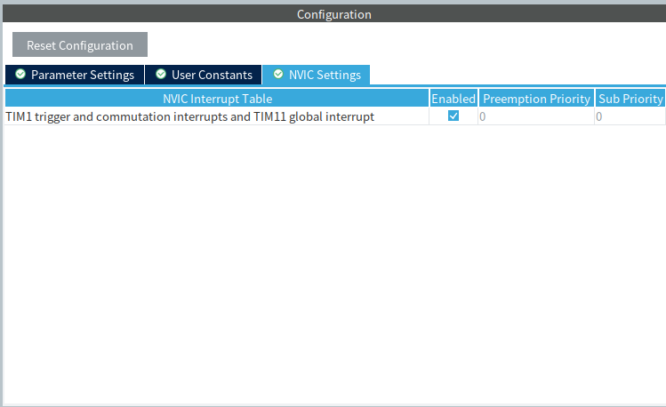
HAL_TIM_Base_Start_IT(&htim11);main함수의 initialize 칸에 타이머 11의 비교일치 인터럽트로 초기화시켜준다.
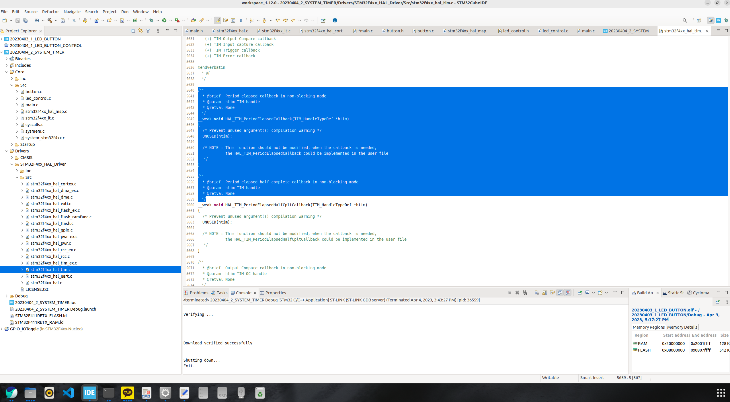
/home/jiwon/STM32CubeIDE/workspace_1.12.0/20230404_2_SYSTEM_TIMER/Drivers/STM32F4xx_HAL_Driver/Src/stm32f4xx_hal_tim.c 에 들어와 콜백함수를 잘라내 메인에 복사한다.
volatile unsigned int timer_1ms = 0;
volatile unsigned int timer_11_1ms = 0;
 void HAL_SYSTICK_Callback(void)
{
  timer_1ms ++;

}

 /*//home/jiwon/STM32CubeIDE/workspace_1.12.0/20230404_2_SYSTEM_TIMER/Drivers/STM32F4xx_HAL_Driver/Src/stm32f4xx_hal_tim.c code
  * enter here every 1ms
   */
void HAL_TIM_PeriodElapsedCallback(TIM_HandleTypeDef *htim)
 {
	if(htim->Instance == TIM11) //타이머 구조체의 시작번지가 11번째면
	{
		timer_11_1ms = 0;
	}
 }
잘라낸 후 메인에서 코드를 수정해준다.
/*
 * led_control.c
 *
 *  Created on: Apr 3, 2023
 *      Author: jiwon
 */


#include "led_control.h"
#include "stdint.h"

uint8_t state = 0;
uint8_t tmp = 0;
uint32_t prev, curr;

extern unsigned char current_button_status[BUTTON_NUMBER];
extern volatile unsigned int timer_1ms;
extern volatile unsigned int timer_11_1ms;

int led_indecator = 0;
void led_all_on_off()
{
	if(timer_11_1ms >= 200)
	{
		if(!led_indecator){
			led_all_on();
			led_indecator = 1;
		}
		else{
			led_all_off();
			led_indecator = 0;
	    }
	timer_11_1ms = 0;
	}
}
void led_main()
{
	timer_1ms = 0;
	while(1)
	{
		one_button_processing();
	}
}


void one_button_processing()
{

	if(get_button(BUTTON0_GPIO_Port, BUTTON0_Pin, BUTTON0) == ACT_PUSHED)
		{
			state = state + 1 % 8;
		}
		else if(get_button(BUTTON0_GPIO_Port, BUTTON1_Pin, BUTTON1) == ACT_PUSHED)
		{
			led_all_on();
			HAL_Delay(1000);
			led_all_off();
			state = 1;
		}

	switch(state)
	{
	case 0 :  led_all_off(); led_all_on();
			break;
	case 1 : led_all_off(); led_all_off();
			break;
	case 2 : led_all_off(); led_blink_up();
			break;
	case 3 : led_all_off();
			led_blink_down();
			break;
	case 4 : led_all_off();
			led_sequential_up();
			break;
	case 5 : led_all_off();
			led_sequential_down();
			break;
	case 6 : led_all_off(); led_flower_on();
			break;
	case 7 : led_all_off(); led_flower_off();
			break;
	default : state = 0;
	}
}
void led_all_on()
{
    HAL_GPIO_WritePin(GPIOB, 0xff, GPIO_PIN_SET);

}

void led_all_off()
{
    HAL_GPIO_WritePin(GPIOB, 0xff, GPIO_PIN_RESET);

}

void led_blink_up()
{
	if(timer_1ms > 200)
			{
			tmp = (tmp + 1)%8;
			timer_1ms = 0;
		    HAL_GPIO_WritePin(GPIOB, 0xff, 0x0);
		}

    HAL_GPIO_WritePin(GPIOB, 1<<tmp, 0x01);
}

void led_sequential_up()
{
	uint8_t temp1;
	if(timer_1ms > 200)
			{
				timer_1ms = 0;
				tmp = (tmp + 1) % 9;

			}
	temp1 = ~(0xff << tmp);

    HAL_GPIO_WritePin(GPIOB, temp1, 0x01);


}

void led_sequential_down()
{
	uint8_t temp1;
	if(timer_1ms > 200)
	{
		timer_1ms = 0;
		tmp = (tmp + 1) % 8;

			}
		temp1 = (0xff >> tmp);
	    HAL_GPIO_WritePin(GPIOB, temp1, 0x01);

}

void led_blink_down()
{

	if(timer_1ms > 200)
	{
		timer_1ms = 0;
		tmp = (tmp + 1) % 8;
		HAL_GPIO_WritePin(GPIOB, 0xff, 0x0);
			}
	HAL_GPIO_WritePin(GPIOB, 0x80>>tmp, 0x01);

}


void led_flower_on()
{
	uint8_t temp1, temp2;
		if(timer_1ms > 200)
			{
				timer_1ms = 0;
				tmp = (tmp + 1) % 4;

			}
			temp1 = ((0x1f << tmp) & 0xf0);
			temp2 = ((0xf8 >> tmp) & 0x0f);
			HAL_GPIO_WritePin(GPIOB, temp1 | temp2, 0x01);

}

void led_flower_off()
{
	uint8_t temp1, temp2;
	if(timer_1ms > 200)
	{
		timer_1ms = 0;
		tmp = (tmp + 1) % 4;
//		HAL_GPIO_WritePin(GPIOB, 0xff, 0);
	}
	temp1 = ((0xf0 >> tmp) & 0xf0);
	temp2 = ((0x0f << tmp) & 0x0f);
	HAL_GPIO_WritePin(GPIOB, (temp1 | temp2), 0x01);
}
이제 led control.c를 수정하고, 보드에 업로드한다. 그러면 아까처럼 200ms마다 LED가 토글된다.
동영상
USART 2
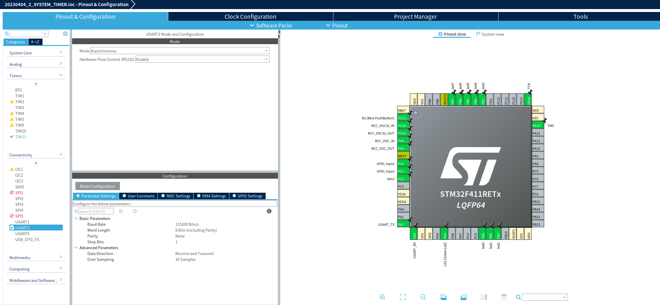
먼저 USART2을 활성화 시킨 후 보레이트를 115200으로 맞춘후 저장을 해준다.
 //----------  printf start ----------
 #ifdef __GNUC__
 /* With GCC, small printf (option LD Linker->Libraries->Small printf
    set to 'Yes') calls __io_putchar() */
 #define PUTCHAR_PROTOTYPE int __io_putchar(int ch)
 #else
 #define PUTCHAR_PROTOTYPE int fputc(int ch, FILE *f)
 #endif /* __GNUC_ */
 /**
   * @brief  Retargets the C library printf function to the USART.
   * @param  None
   * @retval None
   */
 PUTCHAR_PROTOTYPE   // Add for printf
 {
   /* Place your implementation of fputc here */
   /* e.g. write a character to the USART3 and Loop until the end of transmission */
   HAL_UART_Transmit(&huart2, (uint8_t *)&ch, 1, 0xFFFF);

   return ch;
 }
 //----------  printf end ----------
다음 printf를 사용하기위해 위의 코드를 main에 추가해준 뒤, main함수에 printf문을 추가해준다.
/* USER CODE BEGIN Header */
/**
******************************************************************************
* @file : main.c
* @brief : Main program body
******************************************************************************
* @attention
*
* Copyright (c) 2023 STMicroelectronics.
* All rights reserved.
*
* This software is licensed under terms that can be found in the LICENSE file
* in the root directory of this software component.
* If no LICENSE file comes with this software, it is provided AS-IS.
*
******************************************************************************
*/
/* USER CODE END Header */
/* Includes ------------------------------------------------------------------*/
#include "main.h"
/* Private includes ----------------------------------------------------------*/
/* USER CODE BEGIN Includes */
#include "led_control.h"
#include <stdio.h>
/* USER CODE END Includes */
/* Private typedef -----------------------------------------------------------*/
/* USER CODE BEGIN PTD */
/* USER CODE END PTD */
/* Private define ------------------------------------------------------------*/
/* USER CODE BEGIN PD */
/* USER CODE END PD */
/* Private macro -------------------------------------------------------------*/
/* USER CODE BEGIN PM */
/* USER CODE END PM */
/* Private variables ---------------------------------------------------------*/
TIM_HandleTypeDef htim11;
UART_HandleTypeDef huart2;
/* USER CODE BEGIN PV */
/* USER CODE END PV */
/* Private function prototypes -----------------------------------------------*/
void SystemClock_Config(void);
static void MX_GPIO_Init(void);
static void MX_USART2_UART_Init(void);
static void MX_TIM11_Init(void);
/* USER CODE BEGIN PFP */
extern void led_main();
extern void led_all_on();
extern void led_all_off();
extern void led_blink_up();
extern void led_blink_down();
extern void led_flower_on();
extern void led_flower_off();
extern uint32_t prev;
extern void one_button_processing();
extern void led_sequential_up();
extern void led_sequential_down();
/* USER CODE END PFP */
/* Private user code ---------------------------------------------------------*/
/* USER CODE BEGIN 0 */
/*
1. call by SysTick_Handler of stm32f4xx_it.c
2. add void HAL_SYSTICK_Callback(void) in main.c
3. move to here
Arm default timer - it will enter here every 1ms
*/
volatile unsigned int timer_1ms = 0;
void HAL_SYSTICK_Callback(void)
{
timer_1ms ++;
}
//---------- printf start ----------
#ifdef __GNUC__
/* With GCC, small printf (option LD Linker->Libraries->Small printf
set to 'Yes') calls __io_putchar() */
#define PUTCHAR_PROTOTYPE int __io_putchar(int ch)
#else
#define PUTCHAR_PROTOTYPE int fputc(int ch, FILE *f)
#endif /* __GNUC_ */
/**
* @brief Retargets the C library printf function to the USART.
* @param None
* @retval None
*/
PUTCHAR_PROTOTYPE // Add for printf
{
/* Place your implementation of fputc here */
/* e.g. write a character to the USART3 and Loop until the end of transmission */
HAL_UART_Transmit(&huart2, (uint8_t *)&ch, 1, 0xFFFF);
return ch;
}
//---------- printf end ----------
/* USER CODE END 0 */
/**
* @brief The application entry point.
* @retval int
*/
int main(void)
{
/* USER CODE BEGIN 1 */
/* USER CODE END 1 */
/* MCU Configuration--------------------------------------------------------*/
/* Reset of all peripherals, Initializes the Flash interface and the Systick. */
HAL_Init();
/* USER CODE BEGIN Init */
prev = HAL_GetTick();
/* USER CODE END Init */
/* Configure the system clock */
SystemClock_Config();
/* USER CODE BEGIN SysInit */
/* USER CODE END SysInit */
/* Initialize all configured peripherals */
MX_GPIO_Init();
MX_USART2_UART_Init();
MX_TIM11_Init();
/* USER CODE BEGIN 2 */
/* USER CODE END 2 */
/* Infinite loop */
/* USER CODE BEGIN WHILE */
while (1)
{
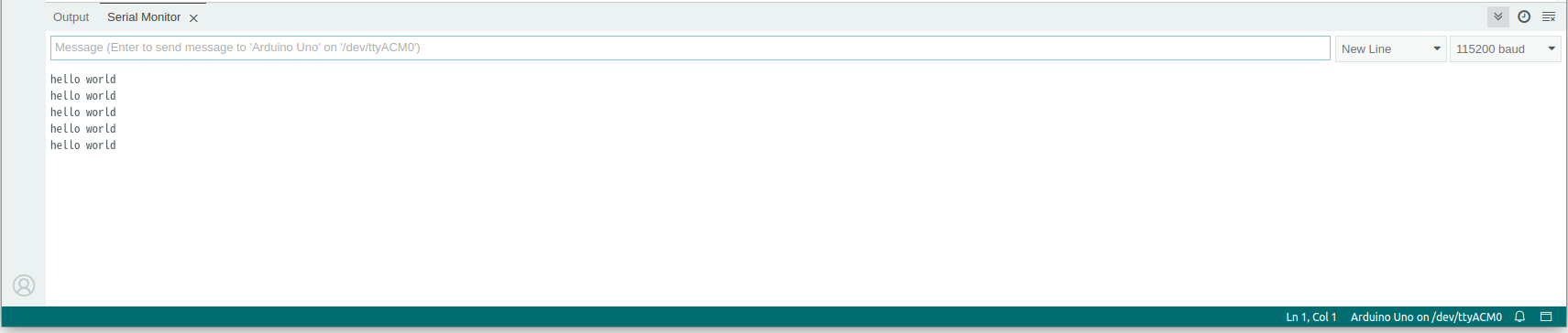
printf("hello world\n");
led_main();
/* USER CODE END WHILE */
/* USER CODE BEGIN 3 */
}
/* USER CODE END 3 */
}
/**
* @brief System Clock Configuration
* @retval None
*/
void SystemClock_Config(void)
{
RCC_OscInitTypeDef RCC_OscInitStruct = {0};
RCC_ClkInitTypeDef RCC_ClkInitStruct = {0};
/** Configure the main internal regulator output voltage
*/
__HAL_RCC_PWR_CLK_ENABLE();
__HAL_PWR_VOLTAGESCALING_CONFIG(PWR_REGULATOR_VOLTAGE_SCALE1);
/** Initializes the RCC Oscillators according to the specified parameters
* in the RCC_OscInitTypeDef structure.
*/
RCC_OscInitStruct.OscillatorType = RCC_OSCILLATORTYPE_HSI;
RCC_OscInitStruct.HSIState = RCC_HSI_ON;
RCC_OscInitStruct.HSICalibrationValue = RCC_HSICALIBRATION_DEFAULT;
RCC_OscInitStruct.PLL.PLLState = RCC_PLL_ON;
RCC_OscInitStruct.PLL.PLLSource = RCC_PLLSOURCE_HSI;
RCC_OscInitStruct.PLL.PLLM = 16;
RCC_OscInitStruct.PLL.PLLN = 336;
RCC_OscInitStruct.PLL.PLLP = RCC_PLLP_DIV4;
RCC_OscInitStruct.PLL.PLLQ = 4;
if (HAL_RCC_OscConfig(&RCC_OscInitStruct) != HAL_OK)
{
Error_Handler();
}
/** Initializes the CPU, AHB and APB buses clocks
*/
RCC_ClkInitStruct.ClockType = RCC_CLOCKTYPE_HCLK|RCC_CLOCKTYPE_SYSCLK
|RCC_CLOCKTYPE_PCLK1|RCC_CLOCKTYPE_PCLK2;
RCC_ClkInitStruct.SYSCLKSource = RCC_SYSCLKSOURCE_PLLCLK;
RCC_ClkInitStruct.AHBCLKDivider = RCC_SYSCLK_DIV1;
RCC_ClkInitStruct.APB1CLKDivider = RCC_HCLK_DIV2;
RCC_ClkInitStruct.APB2CLKDivider = RCC_HCLK_DIV1;
if (HAL_RCC_ClockConfig(&RCC_ClkInitStruct, FLASH_LATENCY_2) != HAL_OK)
{
Error_Handler();
}
}
/**
* @brief TIM11 Initialization Function
* @param None
* @retval None
*/
static void MX_TIM11_Init(void)
{
/* USER CODE BEGIN TIM11_Init 0 */
/* USER CODE END TIM11_Init 0 */
/* USER CODE BEGIN TIM11_Init 1 */
/* USER CODE END TIM11_Init 1 */
htim11.Instance = TIM11;
htim11.Init.Prescaler = 0;
htim11.Init.CounterMode = TIM_COUNTERMODE_UP;
htim11.Init.Period = 65535;
htim11.Init.ClockDivision = TIM_CLOCKDIVISION_DIV1;
htim11.Init.AutoReloadPreload = TIM_AUTORELOAD_PRELOAD_DISABLE;
if (HAL_TIM_Base_Init(&htim11) != HAL_OK)
{
Error_Handler();
}
/* USER CODE BEGIN TIM11_Init 2 */
/* USER CODE END TIM11_Init 2 */
}
/**
* @brief USART2 Initialization Function
* @param None
* @retval None
*/
static void MX_USART2_UART_Init(void)
{
/* USER CODE BEGIN USART2_Init 0 */
/* USER CODE END USART2_Init 0 */
/* USER CODE BEGIN USART2_Init 1 */
/* USER CODE END USART2_Init 1 */
huart2.Instance = USART2;
huart2.Init.BaudRate = 115200;
huart2.Init.WordLength = UART_WORDLENGTH_8B;
huart2.Init.StopBits = UART_STOPBITS_1;
huart2.Init.Parity = UART_PARITY_NONE;
huart2.Init.Mode = UART_MODE_TX_RX;
huart2.Init.HwFlowCtl = UART_HWCONTROL_NONE;
huart2.Init.OverSampling = UART_OVERSAMPLING_16;
if (HAL_UART_Init(&huart2) != HAL_OK)
{
Error_Handler();
}
/* USER CODE BEGIN USART2_Init 2 */
/* USER CODE END USART2_Init 2 */
}
/**
* @brief GPIO Initialization Function
* @param None
* @retval None
*/
static void MX_GPIO_Init(void)
{
GPIO_InitTypeDef GPIO_InitStruct = {0};
/* USER CODE BEGIN MX_GPIO_Init_1 */
/* USER CODE END MX_GPIO_Init_1 */
/* GPIO Ports Clock Enable */
__HAL_RCC_GPIOC_CLK_ENABLE();
__HAL_RCC_GPIOH_CLK_ENABLE();
__HAL_RCC_GPIOA_CLK_ENABLE();
__HAL_RCC_GPIOB_CLK_ENABLE();
/*Configure GPIO pin Output Level */
HAL_GPIO_WritePin(LD2_GPIO_Port, LD2_Pin, GPIO_PIN_RESET);
/*Configure GPIO pin Output Level */
HAL_GPIO_WritePin(GPIOB, led0_Pin|led1_Pin|led2_Pin|led3_Pin
|led4_Pin|led5_Pin|led6_Pin|led7_Pin, GPIO_PIN_RESET);
/*Configure GPIO pin : B1_Pin */
GPIO_InitStruct.Pin = B1_Pin;
GPIO_InitStruct.Mode = GPIO_MODE_IT_FALLING;
GPIO_InitStruct.Pull = GPIO_NOPULL;
HAL_GPIO_Init(B1_GPIO_Port, &GPIO_InitStruct);
/*Configure GPIO pins : PC0 PC1 btn2_Pin */
GPIO_InitStruct.Pin = GPIO_PIN_0|GPIO_PIN_1|btn2_Pin;
GPIO_InitStruct.Mode = GPIO_MODE_INPUT;
GPIO_InitStruct.Pull = GPIO_NOPULL;
HAL_GPIO_Init(GPIOC, &GPIO_InitStruct);
/*Configure GPIO pin : LD2_Pin */
GPIO_InitStruct.Pin = LD2_Pin;
GPIO_InitStruct.Mode = GPIO_MODE_OUTPUT_PP;
GPIO_InitStruct.Pull = GPIO_NOPULL;
GPIO_InitStruct.Speed = GPIO_SPEED_FREQ_LOW;
HAL_GPIO_Init(LD2_GPIO_Port, &GPIO_InitStruct);
/*Configure GPIO pins : led0_Pin led1_Pin led2_Pin led3_Pin
led4_Pin led5_Pin led6_Pin led7_Pin */
GPIO_InitStruct.Pin = led0_Pin|led1_Pin|led2_Pin|led3_Pin
|led4_Pin|led5_Pin|led6_Pin|led7_Pin;
GPIO_InitStruct.Mode = GPIO_MODE_OUTPUT_PP;
GPIO_InitStruct.Pull = GPIO_NOPULL;
GPIO_InitStruct.Speed = GPIO_SPEED_FREQ_LOW;
HAL_GPIO_Init(GPIOB, &GPIO_InitStruct);
/* USER CODE BEGIN MX_GPIO_Init_2 */
/* USER CODE END MX_GPIO_Init_2 */
}
/* USER CODE BEGIN 4 */
/* USER CODE END 4 */
/**
* @brief This function is executed in case of error occurrence.
* @retval None
*/
void Error_Handler(void)
{
/* USER CODE BEGIN Error_Handler_Debug */
/* User can add his own implementation to report the HAL error return state */
__disable_irq();
while (1)
{
}
/* USER CODE END Error_Handler_Debug */
}
#ifdef USE_FULL_ASSERT
/**
* @brief Reports the name of the source file and the source line number
* where the assert_param error has occurred.
* @param file: pointer to the source file name
* @param line: assert_param error line source number
* @retval None
*/
void assert_failed(uint8_t *file, uint32_t line)
{
/* USER CODE BEGIN 6 */
/* User can add his own implementation to report the file name and line number,
ex: printf("Wrong parameters value: file %s on line %d\r\n", file, line) */
/* USER CODE END 6 */
}
#endif /* USE_FULL_ASSERT */이제 리셋을 누를 때마다 시리얼 통신이 잘 되는것을 볼 수 있다.
'ARM' 카테고리의 다른 글
| ARM-5 SPI (0) | 2023.04.16 |
|---|---|
| ARM-3 Timer (0) | 2023.04.10 |